A VLSI design tool from the 1990's is Magic. I was a bit surprised to find that it is still around. But when I tried using it I had more problems than my lack of memory on how to use it.
It was easy enough to install as a current rpm package is available. ("yum install magic" does the trick) This installed version 8.0 revision 60. But there was a big problem: the default scmos technology file was broken. After a bit of reading at the magic web pages I noticed that considerable fiddling with the tech file format had happened. I thought that perhaps this version of magic wasn't happy with the older (version 28) tech file that came with it. So I grabbed the scmos8m.tech and tried it. (adding "-T scmos8m" to the command line) That eliminated the long list of errors at startup and the design rule checker was working. (complaining). (Later I grabbed the latest source code and compiled which fixed the problem with the default tech file.)
Recently I noticed that a schematic representation of the 1802 control circuit had appeared at Visual Chips. A while I after I posted news of this to the Yahoo cosmacelf group, someone created a simulation of some bits of it. One bit was an eight stage Johnson counter that controls the operation of the 1802. This counter is made up of two basic parts that get repeated. Thus it didn't look too difficult a task to whip that up in Magic.
The first thing I laid out was the basic transparent latch:

It is called transparent because in one state whatever is on the input flows straight through to the output. In the other state it simply holds its current value. In this counter these states are controlled by the system clock. When the clock is low(high) the latch is transparent and when the clock is high(low) it holds. (The exact phase relationship depends on how it is connected to the clock signals.)
A quick diversion into how Magic represents things. Green is n-diffusion, brown is p-diffusion and red is polysilcon. Where polysilicon crossed over diffusion you get a transistor. Blue is the first metal layer and purple is the second metal layer. The squares are just the contacts between the various layers.
An inverter is a pair of transistors (n and p) with their gates driven by the same signal, power to the source and the drains connected to each other. There are two in the center of this layout.
There are also two transmission gates. (TG) A CMOS transmission gate is another pair of n and p transistors but their gates are driven by complimentary signals so that if the n transistor is off so is the p transistor. (They are also both on at the same time as well.) This is a simple switch and a signal on one side will be connected to the other. Direction of current doesn't matter.
One transmission gate (the upper) connects the output of the top inverter to the input of the lower inverter. When this TG is on the inverters will hold their state. The other inverter connects an input signal to the input of the lower inverter. Because these are connected to opposite phases of the clock, when one TG is on, the other is off.
The other building block for the counter is a latch with a reset input:
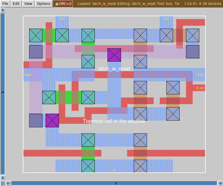
This is mostly the same as the basic latch but the lower inverter has been replaced with a two input NAND gate. (Two n transistors in series and a pair of p transistors in parallel.) One input is the input signal as before but the other is an active low reset input. If reset is low it doesn't matter what the input or TGs are doing, the output will be low.
The full eight stage counter is built up from four of each of these in strict alternation. One thing that should be clear from the transparent operation of these latches is that if all eight stages are in the transparent mode at the same time, the behavior will be extremely boring. (In this case because there is an inverter in the overall feedback loop, it would make an oscillator.)
Once I had those building blocks in hand I assembled them into a full eight stage counter. The layout of the block follows roughly the layout in the 1802 die image. (I actually started with a simple two stage counter, then once that worked expanded to four. Which was a good plan as I ran into a problem which was easier to work out that way.)

Just like in the 1802 there are four stages on the left and four on the right. Signal flow is out of the top left (inverted output is used here only) and into the top right (cells on the right have been rotated 180 degrees). The groups of four are connected to each other and the final connection is out at the bottom right and into the bottom left.
Also included here is the pair of inverters used to drive the TG control lines. I included them here because they add delay and that delay causes trouble in the operation of the latches that I wanted to capture. Or at least not ignore. On the die the inverters are built from one n transistor and two p transistors in parallel. This is because the charge carriers in p type MOSFETs (holes) are less mobile than the electrons in n type MOSFETs so they have a higher on resistance. This equalized the rise and fall times. Since I am not using C2L I could simply make the p transistors wider.
With the Magic layout in hand I could then have Magic extract the layout information and then convert that into a file suitable for IRSIM. One concern I had was the extensive use of transmission gates in this circuit. From past experience I know that this can cause trouble.
I had no problems with the two stage counter but when I moved on to the four stage version there was trouble. Instead of nice counting action I saw undefined levels. A quick check back with the IRSIM web page and I found just the thing: the "settle" parameter (read more about it in the IRSIM tutorial) fixed this problem. 1ns wasn't enough but 2ns did the trick.
When I then tried the full eight stage counter I had to increase the settle value to at least 4ns. This is because the root of the problem is that the clock drivers have some delay which means that the transmission gates get switched at different times and this leads to conflicts with two things trying to drive one node to different voltages. As I add stages I add more gates that need to be driven and more capacitance which increases the rise/fall times.
But with that out of the way the simulation worked great:

The top signal is the clock (not the output of the clock drivers but the signal provided by the sim) with the outputs of the various stages below. The simulation does exhibit some interesting behavior.
The first is something that I expected: it can take up to half a clock for a reset to fully take effect. This is because only half the latches have a reset input and if the following stage without a reset is in its hold phase, it will not be reset until the following half cycle.
The other I didn't expect but after more thought is correct. I noticed that coming out of a reset both the seq0 and seq1 outputs would go high in the same half clock period. But this depended on the phase of the clock. After a bit of thought I realized that this was another problem caused by delays in the clock drivers. The reset signal is provided by the simulator and thus has zero delay. If I set reset high and then clock the circuit, reset goes high before the clocks change. If the first stage is in transparent mode, the high input will start its progress through the circuit as soon as reset goes high. A bit later the clocks switch it to hold mode. But of course this also changes the following stage from hold to transparent so that logic high value propagates through both of them.
Perhaps reading this has inspired (or perhaps damaged) you enough so that you would like to play with Magic and IRSIM. Here are the Magic design files:
Note that you have to have all three to see the full counter. Also, these a plaintext files so you could read them if desired.
With those you could make your own file for IRSIM but in case you don't want to mess with Magic:
The command file has some tedious (after you do it a few times) setting up exercises. Note that the command file sets the reset input low. You will want to clock the simulation once and then bring it high ("h reset") to start the counter.
The details of using Magic and IRSIM are beyond the scope of this page but there are excellent tutorials on their web sites.
Home