
This launch controller is designed primarily for use with standard DARS model rails which have three pads per rail. The controller supports two rails for a total of six pads. The controller can also be used with the DARS relayers to support high power rockets.
The design of DARS controllers has evolved over the years and this is just the latest version. It (hopefully) corrects some of the problems of previous controllers and doesn't add any new ones. The starting point for this design was the 'Boris' controller (DARS also has a controller named 'Natasha'). Boris had a few known problems. The worst of which was that it used N type MOSFET's to switch the positive voltage rail. If this doesn't ring a bell, I will explain. In order for a N type MOSFET to turn on, the gate must be a certain minimum voltage above the source pin of the FET. The source is connected to the output that goes to the igniter. Because of this gate to source voltage requirement, there is always a drop of several volts across the FET. This drastically limited the current available. The obvious and simple solution is to use N channel FET's to switch the low side of the circuit.
Another problem with Boris was that the CMOS inverters used in the continuity circuits would fail fairly frequently. While most CMOS parts have clamping diodes on their inputs to protect from electro-static discharge, they have a tendency to fail if abused. A 100K resistor has been placed in series with these inputs and this should limit the fault currents and increase the lifespan of these parts.
The most significant new feature of this controller is that the majority of the wiring is now on a printed circuit board. This eliminates the rats nest of wire wrap wire that previous controllers have had. The downside is that to get everything to fit, several surface mount parts are used. Don't panic, surface mount isn't that difficult. At least if you know your limitations. I for one will not use discrete components smaller than 0805 size and try to avoid those if I can.
The design first entered service in the summer of 2004 and the only failure so far (late 2005) has been a broken wire that was caused by an overzealous application of force to a crimp type spade lug.
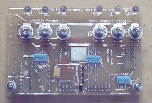
Here is a photo showing two controllers at a recent launch.
The controller is protected against reverse battery polarity.
When the controller is "safed", two failures are required to get power to an igniter.
Audible indication of one pad selected, multiple pads selected, and armed.
Pad continuity status indicated by LED's
The printed circuit board contains circuitry for continuity test, pad select, and status monitoring.

(Full schematic in pdf format.)
The continuity test circuit is fairly simple and uses a CMOS inverter as the active element. Do not substitute for the 74HCT14 unless you verify that the input logic transition levels are compatible. In addition, 4000 series CMOS does not have sufficient current drive to operate the LED's.
A 100K resistor in rn1 pulls each input down to ground. This input goes to the low side of the igniter (which is also the drain on the output FETs). The other side of the igniter goes to the output of the arming relay. There is also a 5K resister to the 5V rail tied to the output of the arming relay. This provides current limited power which pulls the input of the inverter high when an igniter is attached. Normal continuity current is about 50 microamps.
The continuity test inputs are exposed to 12V and ESD. The inverter inputs do have protection diodes that clamp the input voltage to the power and ground rails but they can handle only limited current. The 100K resistor (rn2) limits the fault currents when these diodes conduct so that the inverter isn't damaged.
High brightness red LEDs are used so that they are visible even on a bright sunny day.

The pad select circuits connect the FET gates to the firing switch. Another inverter is used to monitor the switch position.
When the controller is armed and the launch button is pressed, 12 Volts will be connected to the "Launch Req" line tied to the pad select switches. If the switch is in the selected position, 12V will be routed to the gate of that pads FET. The zener diodes limit the gate voltage to 20V which is the typical absolute maximum gate to source voltage of most power FETs. This is just in case we ever decide to use a 24V power source. Not very likely but it could happen. The zeners can be skipped if you will only operate on 12 Volts.
RN4 provides a pulldown to the gate of each FET to make sure that they stay off unless the launch button is pressed.
RN4 also provides one pulldown resistor that is connected to the common side of the pad select switches. When a pad is selected, the input of the inverter will be pulled high by RN6. When a pad isn't selected the RN4 pulldown will pull the inverter input low. The inverter output goes to the input of a PIC micro-controller.
If either of the inverters fails, they are easily replaced because standard DIP package parts are used and they are socketed. Hopefully with the new 100K resistors in series with the inverter inputs, they will never fail. But because of past experience with the Boris controller, they are socketed.

Monitoring and alarm functions are provided by a PIC micro-controller. If you leave out the micro-controller, you can still launch rockets but you will will not get the audible warnings.
The pad select status is used to turn on a pad select warning. When a single pad is selected, the piezo buzzer produces a series of single beeps. When more than one pad is selected, the piezo buzzer produces a series of double beeps. This provides some feedback to the operator in the hope that it will prevent inadvertent drag races.
The "PYRO" line is tied to the output of the arming relay. The voltage on this node is monitored and when it is above the 5V used to power the continuity testing, the piezo buzzer sounds continuously. This provides an audible controller armed warning when the arming key is turned. If a continuous tone is heard and the key is in the safe position, then the most likely cause is a welded relay and the controller should be repaired.
A diode (D14) and 5K resistor provide the current limited power for the continuity circuits discussed previously.
A dual color LED is used to provide battery status. Green indicates the battery voltage is at least 11.5 Volts. Yellow means more than 10.5 Volts but less than 11.5 Volts. Red indicates less than 10.5 Volts. This was used instead of the usual panel meter due to lack of space for a panel meter. It doesn't provide as much information but it should prove useful anyway. The transition voltages are software controlled so if you don't like them, you can pick whatever you like by modifying the source and recompiling.
If you want to build one of these circuit cards, you will first need to grab the design file for the printed circuit board. Then you will have to order your pcb's from expresspcb. You have to download and install their software in order to order the boards. This card was designed to fit the requirements for miniboard service. For $51 plus $9 shipping (Feb. 2005 price) you will receive three double sided boards with plated through holes. No silk screen or solder mask though.
With the cards in hand you can mount all of the parts. (See parts list.) Start with the surface mount parts, proceed to the remaining parts except for the toggle switches and LED's. To install these you will need to build a simple jig. Don't put the IC's into their sockets yet.
Soldering surface mount parts isn't too difficult. The trickiest part is getting the part where it needs to be. Once you do this, tack down a lead on opposite corners (this applies mainly to parts with more than two leads) and then inspect the orientation again. It is a lot easier to tweak it now than after all of the pins are soldered. If you should happen to create a solder bridge on one of the resistor packs, don't panic. Get a solder sucker (I use a spring loaded one) and remove the excess solder. I find that this removes the bridge but leaves enough solder behind for a good connection although I sometimes have to touch it up a bit. You can reflow the remaining solder by touching the soldering iron to the pin. Because the iron is dry and you aren't adding any more solder, you will not create a solder bridge.
The jig is just a sheet of material with the same thickness as the panel you will mount the card to. Drill holes in the jig for the standoffs, switches, and LED's. Then slip the switches into their mounting holes (no solder yet!) and bolt the card to the jig using the standoffs. Now tighten up the mounting nuts on the switches (one goes under the panel and the other on top) and make sure they are evenly aligned the way you want them. Once the switches are the way you want them, solder them in place.
Push your LED retaining clips into the jig. Now slide the LED's into the pcb and then push it into the retaining ring. Be sure that you get the polarity on the LED's correct. Making sure that the LED is flush with the retaining clip, solder its leads and trim.
You can now remove the card from the jig. If everything worked correctly, it will fit perfectly into your front panel with the LED's and switches at the correct height.
Now clean the circuit card to remove the solder flux. Isopropol alchohol works very well. Let dry and then for added protection, give the card a conformal coating (I found spray conformal coat at the local Fry's Electronics) to protect it. You will need to use masking tape to protect the sockets, voltage regulator, switches, LED's, and connector. You may want to postpone this until after you have had a chance to verify that the card is working correctly as it will be easier to make repairs before coating it.
Be sure to program the PIC with its firmware (source) before installing it in its socket.
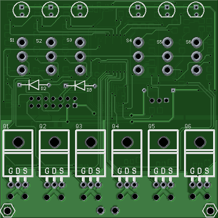
Here are a couple of pictures of a completed circuit card:

With the printed circuit card complete that the leaves the remaining wiring which mostly carries the high current loads.

The schematic is also available in acrobat format.
There is no formal parts list for this part as individual tastes may vary.
I used a four pin connector normally used for microphones to bring 12V power into the controller for no better reason than it is compatible with power cords used on other DARS controllers. Use whatever connector (or no connector) you like but be sure to give some thought to how much current it will have to carry.
The ammeter is used to give some feedback to the operator as to what is happening when the launch button is pressed. Choose a meter that reads a minimum of 20 amps. 50A would be better.
The relay is a typical automotive 12V relay rated at either 30 or 40 amperes. Some relays come with built in diodes. Be sure to get the polarity right if it has a diode and install an external diode (1N4000 series) if it doesn't. Put the relay in a socket so that it is easy to replace when it fails. Since these relays are pretty cheap, you might even consider replacing the relay every year or two even if it hasn't failed. Because the relay is being switched "dry" (no load), it should last a very long time but experience may indicate otherwise.
The power switch does not have to be rated for more than an amp or two as it does not switch significant current. Use whatever you like.
Use whatever key switch and launch button you like. Be sure that the key can only be removed in the safe position. We found some really nice push button switches with good tactile feedback (2PB12-T2) in our junk boxes. (I purchased mine at the Sandia National Labs salvage yard in the 1970's.) They are very nice but haven't been made in over a decade. You can still find a few as "new old stock" but $21 (here is one source) apiece might be too much for your tastes.
The piezo alarm is just a generic item found at Radio Shack.
The power MOSFET's should be good high current NMOS types (such as the IRFZ44) and be mounted to individual heatsinks. They aren't likely to get very hot in normal use but the heatsink will protect them from unusual situations. The heatsinks must be isolated from each other or the pad outputs will be tied together.
DARS uses cables based on six pin Cinch Jones plugs for connecting to the model rails. Note that for this controller, the common is not ground but positive.
This design has been the workhorse for DARS for 13 years now and has proven itself. I decided that it could benefit from a few changes. I no longer use PIC micro-controllers so I switched to a MSP430. While the CMOS inverters haven't been a problem, I think that a Darlington transistor array will work a little better. The major change is moving the power FETs onto the PCB.
This last change is a bit of a risk. It will make assembly of the controller easier but high current and printed circuit boards usually don't work well together. I have beefed up the high current paths but only use will show if it works.
Most of the parts on the other side are surface mount. Assembly can go a little faster if you use a solder stencil and reflow but it can also be done by hand.
The design has been moved from the proprietary CAD package from ExpressPCB to the gEDA system. I usually use OSHPark for PCBs. They charge $5 per square inch and 3 copies. So this 3"X3" board runs $15 apiece.
Schematic(pdf)
As before the only function of the micro-controller is to provide feedback to the operator. It counts the number of pads selected, and measures the battery voltage.
Starting in the upper left corner of the schematic and going clockwise, the first circuit is the ULN2803 Darlington array. If no igniter is connected at the pad then the resistors in the ULN2803 pull the transistor base down and it and the LED are off. When an igniter is connected, this pulls up the base (via VPYRO, <3.3V) turning on the transistor and LED.
The two remaining Darlington pairs are used to drive the piezo alarm. One pair is controlled by the MSP430 and indicates when one or more pads are selected. The other pair detects when the arming relay is closed. Providing a constant alarm tone. Z1 makes sure that the 3.3V provided for continuity testing doesn't spoof the circuit.
The upper right circuit is the connector to the off board parts and the voltage regulator that powers the MSP430. D1 provides reverse battery protection while D3 controls the inductive kick from the arming relay. D2 and R29 provide a current limited excitation voltage for the continuity circuit.
In the lower right are the pad select switchs and power FETs. The Zener diodes are optional. They are mostly to protect from excess gate drive if a battery of greater than 12V is used. But they also protect the sensitive gates of the FETs from ESD so are highly recommended.
The MSP430 micro-controller is in the lower left. This is programmed via Spy-By-Wire. Programmers are readily available from TI. Practically every LaunchPad board includes one and they can be readily used to program parts off board.
Six pins are unused and are available for other uses.
This time around I used discrete resistors instead of arrays. More parts to place but it simplified the PCB layout.
The remainder of the wiring is pretty simple. If I wasn't worried about compatibility with the other DARS equipment I would use Powerpole connectors for all of the battery and pad cables.
I haven't built one yet simply because DARS seems to have plenty of launch controllers at the moment.