
For when 200SPS just isn't enough.
I wanted to get some gyro data at a rate high enough so that launcher dynamics could be seen. After looking at the low cost MEMS devices I settled on the MPU-6000/9250 because they can provide data at up to 32,000SPS. That is a lot of data and while I might be able to press my usual micro-controller (MSP430) to do that, a faster ARM based processor would be a better fit.
The Teensy 3.6 is fast enough and will be spinning its wheels most of the time. The one feature that triggered my purchase was that it had a micro-SD card socket on board and it used a high speed (up to 50MHz) 4 bit wide SDHC interface in the ARM processor.
The Teensy 3.6 of course and for the MPU-9250 I purchased a breakout board. That web site is no longer responding alas. The board was configured for I2C and required some minor changes for SPI. I glued the board onto the back of the Teensy 3.6 and soldered wires between them.
For power I am using a 2 cell LiPo battery. The voltage is above the maximum given for the Teensy 3.6 but digging out the data sheet for the voltage regulator it is good to 10V. There is a diode on board so reverse polarity will not damage it. I left the connection between Vin (external power) and Vusb intact so it is critical that only one power source be connected at a time.
Battery capacity is 200mAh which should be more than adequate. Current requirements during operation are about 50mA average. Once the flight is complete this drops to about 3mA. One charge should be good for several flights.
The Teensy 3.6 is intended for use with the Arduino environment but I don't care for that. But a full GNU C compiler is installed along with the rest of the baggage and it is simple enough to use that on its own. Debugging is another story as you can't use the gdb debugger without some external hardware to access the JTAG port. (Assuming that the bootloader processer would get out of the way, which it doesn't.)
While I did some initial poking around and speed testing of the SDHC hardware in C I switched to Forth for the actual logging code. I ported over the version of eForth that I had working on the MSP430. With that working, I had a the entire development environment running on the Teensy 3.6.
I thought this would be easy but I was wrong. With the CPU clock at 120MHz there are about 3,750 CPU cycles between interrupts. This seems like plenty since it only requires 720 of them to transfer all of the MPU data over the SPI bus at 20MHz. But the high level Forth version was too slow and even using an assembly language routine to write the SPI port didn't help enough.
I ended up having to write the routine to do the SPI transfer in assembly to make it fast enough. I took care to make sure no time on the SPI bus was wasted. I was looking into using the eDMA system but it is a complicated system and while I was trying to figure it out I decided to give assembly one last shot. That managed to get close enough to the minimum so that I didn't think that the eDMA system could provide much improvement.
Then I ran into hassles with the ARM low power system. I thought that putting the CPU to sleep when there was nothing for the buffer write routine to do would help with power consumption. It does, but it is also slow.
I guess I am spoiled by the MSP430 low power modes. An MSP430 using the DCO wakes up essentially instantly. The ARM, not so much. The data sheet for this ARM CPU shows that going from STOP mode to RUN requires up to 5.4us. An eternity when there are only 31us between interrupts. This is enough to be a concern. Fortunately seven out of eight times it only reads the gyro data so finishes faster. Testing showed that it wasn't causing any missed samples. Yet. So for now I will keep including data from the PIT to check for problems.
Another thing I like about the MSP430 is that the interrupt service routine can decide if the CPU should go back to the low power mode when it finishes. This would be handy since the control task only needs to run when new 4KHz data is available so waking it up at 32KHz is a waste.
The primary job of the foreground task is to write data to the micro-SD card. Because the simple DMA system in the SDHC interface is used, it doesn't consume too many cycles doing this. A write can actually proceed while the ISR is gathering data which is very nice.
The other job is deciding when to stop recording data. Each flight is allocated 32MB of storage space which is treated as a large ring buffer. Once launch is detected (using the accelerometer data), the current location in the data file is noted. Then when the current location reaches a point two seconds before that, it stops recording. It then records that position elsewhere (normal Forth BLOCK storage). 32MB provides only 128 seconds of data but I am interested in only the launcher dynamics now so it is plenty.
I have been using a fancy new 16GB micro-SDHC with a speed class 10 rating. You would think that would be plenty fast but it isn't. The detail is that to achieve that speed you have to write data in Recording Unit (RU) sized chunks. Until version 5 of the SD specification was released last year, the only information on just how big an RU was was that it was a multiple of 16K. But version 5 added a lot of detail on speed ratings and now it says that in some cases (speed class 10, SDHC) the RU is 512K. Writing data in chunks that big is difficult on a micro-controller with only 256K of RAM.
I noted some ~90ms stalls when writing in 4K chunks which isn't too awful but they occurred in consistent bursts of 4 or 5. That meant that I had to have at least a half second of buffer space in RAM or 128K. Not impossible but very annoying. Changing to 16K writes improved performance quite a bit. I still allocate 9 16K buffers so a half second stall can be tolerated.
The code to write a buffer includes toggling the LED so it gives an indication of SD card write speed. It normally is fairly dim but periodically gets brighter when there is a stall.
One of the PIT timers is enabled in essentially a free running mode and its 32 bit count is included in the 4KHz data. This provides a timing reference since the MPU-9250 clock is not crystal accurate and allows for an easy check for missed samples.
Launch is detected in an orientation agnostic fashion using all three accels. Square each, add together, and take the square root.
This is converted to meters/second, a 2 m/s bias and the 1G offset are subtracted, and it is then integrated. If the result is negative, it is set to zero. This makes sure that any offset error will not cause a gradually increasing velocity. When the velocity reaches 10m/s, that is considered to be a valid launch.
There is a lot of data to deal with. The MPU-9250 interrupts at ~32KHz signaling new data is available. The accelerometers are only running at 4KHz so they are read once every eight interrupts. The data needs to be stored in a way that facilitates its use later. I decided to use an old technique from PCM telemetry: sub-multiplexing. In this method a data slot is used to store lower rate data.
At every interrupt 8 bytes of data are stored in the buffers. The first six bytes are the new gyro data. The last two bytes are used for the slower data.
| subframe # | ||||
|---|---|---|---|---|
| 0 | Z gyro | Y gyro | X gyro | temperature |
| 1 | Z gyro | Y gyro | X gyro | Z accel |
| 2 | Z gyro | Y gyro | X gyro | Y accel |
| 3 | Z gyro | Y gyro | X gyro | X accel |
| 4 | Z gyro | Y gyro | X gyro | ADC 0 |
| 5 | Z gyro | Y gyro | X gyro | ADC 1 |
| 6 | Z gyro | Y gyro | X gyro | CVAL 0 |
| 7 | Z gyro | Y gyro | X gyro | CVAL 1 |
On a real PCM encoder you would also add a frame synchronization pattern and frame counter. I don't need that here because both the minor frame size (8 bytes) and major frame size (64 bytes) divide the SD block size (512) evenly. So the frame alignment is fixed and I don't need anything to help figure out where the data is.
You could also look at it as a single 64 byte frame where the gyro measurements are super-multiplexed.Included are about 400 screens worth of the file system. This includes the vocabulary, a screen editor, and the logging code. eForth attempts to load screen 1 at startup unless a jumper is connected. See code for details.
File system imageWrite the image to a micro-SD card using dd or equivalent. (dd if=image.blk of=/dev/sdb size=1k seek=1 count=400) The seek parameter skips over the first 1K on micro-SD card.
Just for a test to make sure everything was working I flew the logger on an Aerotech Initiator with an added electronics bay. The logger worked as expected and the data was even kind of interesting. The raw data is exceptionally noisy and while trends can be picked out, they are more obvious with a little low pass filtering. I used a 10 point moving average filter here.
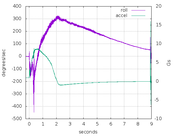
This shows the roll rate and longitudinal acceleration. The first thing that jumps out is that the delay on this G64-4 was more like 7 seconds. Not completely unexpected since the package showed it was manufactured in 2000.
The roll was also interesting. The rate was increasing in the negative direction up until the point where the launch lugs came off the 1/4" launch rod. (Visible as spikes in the data around 0.3 seconds.) Then the direction switched and the rate gradually grew until it peaked around 300 d/s at maximum velocity.
Integration also works as a low pass filter and integrating the roll rate produces a very nice result:
And zooming in to just the first half second and including pitch and yaw:

I suspect that the initial roll was the result of a slight thrust misalignment. Then once in free flight a slight misalignment in the fins (even with a pre-slotted airframe) pushed it the other way.
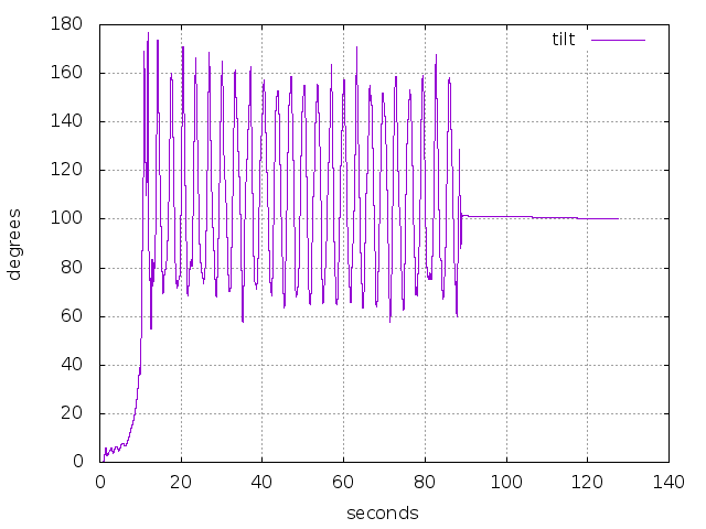
I ran the gyro data through my quaternion based attitude code to get tilt and the data for the full flight is more or less as expected. The oscillation while descending under parachute was expected as the payload bay was hanging upside down and swinging around. The final tilt should be 90 degrees, more or less, depending on just how it ends up laying on the ground plus drift and other errors. So 100 degrees is pretty good.
Zooming in to the early part of the flight until apogee provides a little more detail there:

There is a bit of movement on the 1/4" rod and then it tilts into the wind before starting the long gravity turn to apogee.
A little deeper look at the acceleration data for the ejection shock.