Here you will find plans to build an Ohm meter that can measure up to 2 Ohms (1.999 actually) with 0.001 Ohm resolution. Optionally, a 20 Ohm maximum range can be used in which case the resolution is 0.01 Ohms. The circuit is simple, easy to build, and the parts are readily available.
Several years ago I wanted a meter to check igniters with. The problem is that the lowest range on my vintage Heathkit meter is 200 Ohms. Since igniter resistances are down around 1 Ohm this wasn't very helpful. Not to mention that my test lead resistance could be as large as the igniter resistance.
You can purchase an Ohm meter that would work but they typically cost several thousand dollars which was a bit over my budget. Why so expensive? Because they are carefully designed to limit test currents and control failure modes that would increase them. The average DMM does not come close to doing this. But I figured I could build one easily enough. I needed a controlled current source, an amplifier, and a display. The circuit relies on Ohm's Law ( E=IR ) to measure the resistance by passing a known current through the resistance under test and measuring the voltage that results.
The trick to making this work well is to use a four wire ("Kelvin") connection. This separates the test current and measured voltage into different wire pairs. The result is that the meter does not measure the voltage drop of the test leads. This is not normally a problem unless you want to measure low resistances. Then the test lead resistance can be large enough to impact the reading.
My Heathkit DMM has an offset of about 1.5 Ohms when it is in the 200 Ohm range. If this offset were consistent, you could subtract it from the measured resistance to get the true resistance. But it is rarely stable and it is still limited to 0.1 Ohm resolution so I needed something better.
I used a common LM334 as the current source and picked up an AD521 instrumentation amplifier at a local electronics surplus store (Tanner Electronics) along with an LCD panel meter.
The panel meter had a serious drawback in that it could not share a common ground between power and signal. So I ended up with three 9V batteries. One for the meter and two to provide a bipolar power supply to the instrumentation amp. Not very convenient but I have used it for several years.
I have wanted to improve on the three battery design for a while. So I recently picked up another panel meter to play with. This meter is the PM-128E and the E suffix means that it can be used with a common ground. It turns out that I do not want or need this common ground feature so a different panel meter would work fine.
The PM-128E has a lot of options to select by putting solder bridges in the right places. I set it up for DC voltage, 200mV range and connected switches to the power supply options so I could play with it. You can set the meter up for either a 5V regulated external supply with a common signal and power ground or an unregulated 9V supply with isolated grounds.
After looking over the web I noticed that it looked like most LCD panel meters use the ICL7106 or equivalent chip. Looking at the data sheet I noticed something about the input signal ground that gave me an idea. This is not a ground but an active input that is maintained at a particular voltage by the ICL7106.
The newer instrumentation amps have a lot fewer pins and options than the older units but one thing they do have is a REF input pin. The output of the amp is referenced to the voltage on this pin. It looked like I could connect the GND input of the meter to this pin.
So I hooked up a quick test circuit to see if this would work. It does!
This means that I can now build a new meter that will use only one battery.
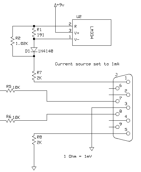
The circuit is pretty simple. The major elements are a current source, an amplifier, and the panel meter.
The current source is the common LM334 and R1 sets the current to about 1mA. Since the LM334 also makes a pretty good temperature sensor and a meter that is accurate at only one temperature isn't too useful, the temperature compensation circuit shown in the data sheet (D1 and R2) is included. Actual current output is not exactly 1mA, but the amplifier gain can be trimmed to compensate for this.
During construction, I epoxy the diode to the LM334Z (TO-92 package) so that their temperatures will be fairly close. R1 and R2 should be quality 1% parts with low temperature coefficients.
The output of the current source then goes through a 2K resistor (R7), out to the test point, and back through another 2K resistor (R8) to ground. These 2K resistors are pretty busy so here is what they are doing:
1) They drop a lot of the battery voltage (4V total) which limits the drop on the LM334. Which limits the self heating. Self heating would cause temperature drift in the current because the diode cannot track this self heating effect very well. The series resistance is only 4K so that I have some operating margin on the 9V battery.
2) The 2K resistor on the ground side of the circuit brings the common mode voltage presented to the instrumentation amp away from ground and towards the center of the supply range. While the inputs of the instrumentation amp can go slightly below ground, the output voltage swing is greatly reduced. I don't think that this is a serious problem but it can't hurt to be careful.
3) They prevent a failure in the current source from allowing excessive current to the igniter. There are now 3 elements in the circuit that limit current and all three must fail or be bypassed in order to get more than 4.5mA (9V/2K) of current to the igniter under test.
A lot of work for just two little resistors. :-)

First up for the amplifier are the 10K resistors (R5 and R6) on the inputs. They are there to limit fault currents if for some reason a voltage outside the supply voltage range ends up on the test clips. The instrumentation amp has diode clamps on the inputs to limit these voltages and the resistors limit the current flow when the diodes conduct. In order to limit offset errors, these should be the same value and 1% tolerance.
The AD623 instrumentation amplifier has two inputs and the resistance on both of these are in the Gigiohm (10^9) range. You can't do this with a simple opamp. The result of this high resistance is that very tiny currents flow through the voltage measurement wires. Which means that we are not measuring the resistance of those wires.
The gain of the amplifier is set by a single resistor on the Rg terminals. We need something a bit more complicated than a single resistor to allow for trimming the gain and changing ranges. If you decide that you don't want both ranges, skip the switch and extra resistors. R3 and R9 should be quality parts with a low temperature coefficient. The variable resistors should be multi-turn.
One thing that this circuit cannot do is trim out the offset. The offset in modern instrumentation amps is a lot better than the AD521 but it still exists. The offset should be less than 1mV at the output so this shouldn't be too big of a problem. It is possible to add offset adjust but it adds several more parts, one of which is only available in a surface mount package. I wanted to keep this design simple and surface mount complicates things too much.
The input offset current error (difference in bias currents between the two inputs) is one of the sources of offset error. The offset current error is about 2.5nA and since R5 and R6 are 1% parts they could be off value by up to +/- 100 Ohms. Maximum error would then be 200 Ohms * 2.5nA = 0.5uV which is acceptable.
A little bit of offset is a pain but acceptable. Most of the time we are not interested in the exact resistance of an igniter down to the milliohm. But there are a couple of circumstances when milliohms count.
1) Checking a Copperhead igniter for shorts. Since you are comparing the resistance near the igniter head to the other end, the difference is what counts so the offset isn't an issue. (If the resistance is lower away from the head, there is a short.)
2) Matching igniter resistances for clusters. OK, maybe matching to the milliohm is a bit too much but again, differences are what count so the offset isn't an issue.
So I decided to go with a simpler circuit and live with the offset.
For the curious, the offset adjust circuit is a variation on what is shown in the INA122 data sheet. Except that the two 100 Ohm resistors are connected to the meter GND pin instead of to ground. And while using the REF200 for this, you might as well replace the LM334 with a REF200 strapped to provide 400uA and adjust the amplifier gains. The thermal performance of the REF200 is a lot better than the LM334.
If you use the PM-128E meter, be sure to set it up for DC 200mV input and 9V power supply. Other 9V powered meters that will measure 200mV DC and use the ICL7106 chip should work fine as well.

I built my prototype using simple point-to-point wiring on a bit of perf board that had pad per hole copper on it. I mounted the DB-9 connector to the board by sliding the board between the two rows of contacts and soldering the contacts to the copper pads on the board. This way when I mounted the connector in the case, I also mounted the card. I found a simple plastic case with a 9V battery compartment to mount everything in. The plastic case made cutting holes for the panel meter, connector, and power switch very easy.
The AD623 is in a socket but nothing else is socketed.
The range select switch not only changes the gain of the amplifier, it also changes the decimal point location on the display. There is a lot of variation in how different displays select decimal point location so you will have to look over your display to figure out how to do it. For the PM-128E that I am using, I had to look over the circuit board to figure it out since the documentation is minimal.
I don't show it but you will need a 9V battery and power switch.
I show a DB-9 connector for the test cable and you will need to build a cable. You will need:
If you plan on testing a lot of Copperheads, build another cable for them using the Aerotech igniter clip.
In order for the meter to work correctly, you must make the connections at the proper location!
Attach one pair of wires to pins 1 and 5, the other pair goes to pins 7 and 8. Connect the shields to pin 3.
Connect the wires from pins 1 and 7 to one of the alligator clips and solder.
Connect the wires from pins 5 and 8 to the other alligator clip and solder.
By making the connections this way, the 1mA test current flows through the wire from pin 1, through the igniter, and back through the wire to pin 5. The wires on pins 7 and 8 measure the voltage on the test clips but zero (nanoamps are close enough to zero for me) current flows. Thus the wire resistance isn't a factor at all.
When on the 2 ohm range, the least significant digit represents a voltage on the igniter of one microvolt. This is pretty small so please use shielded twisted pair wire.
I built my meter and in the process noticed (remembered actually) one very annoying problem. The instrumentation amplifier gain set resistor is very sensitive. So sensitive that just getting your hand near the wires to it or the variable resistor is enough to change the gain. I decided that this would be so sensitive that even after enclosing it in its plastic project box the gain would still be subject to random variations. So I removed the range select switch and left the meter set for 2 ohms.
One other thing to be aware of is that instrumentation amps are sensitive to RF interference. This isn't usually a problem except in strong RF fields. I have never had a problem with this but if you do, add the capacitors as recommended in the AD623 data sheet. Which reminds me that I probably should have included some power supply decoupling capacitors but it seems to work fine without them.
Commercial igniter testers are always (and I do mean always) checked to make sure that the test current is within specifications before each and every use. You probably don't need to be quite that paranoid but an occasional test would be good. Never test igniters after they are installed in a motor or ejection charges that are loaded with black powder. Be sure that the igniter under test is in a safe location so that if it does ignite, you (or anyone else) will not be hurt. Be safe.
To calibrate your meter, first clip the test clips together and make sure that the offset is less than 0.010 ohms. It could be a little larger than this but if it is too large, you want to try and figure out why.
Then hook the test clips to a 1.0 ohm 0.1% resistor (1% is OK if you can't find a 0.1%) and adjust the gain. If your meter has a 20 ohm range, use a 10 ohm resistor. Once adjusted the gain should be fairly stable but you should still check it once a year or so just to be sure. You could also install the test resistors on the same card with the other components (but not connected to anything) just to make sure they are always where you need them.
Besides checking igniters, you can use this meter for other tasks. I frequently use it during DARS equipment cleaning sessions to check igniter clip leads. Just hook the alligator clips together and measure from the other end. A reading of more than a few tenths of an ohm is a sure sign that the clips need work.
You can also test relayers to see what the internal resistance is or to check the relay contacts for wear. Assuming that the relay is switching the positive side, connect one terminal of the meter to the positive battery input and the other to the relayer output. But don't actually connect to the battery. When you pull in the relay, you can measure the relay's contact resistance. If you want to know the total resistance in the circuit, clip the relayers battery clips together and connect the meter to the relayer output. Now when the relay is energized you will measure the total resistance of the relayer. Add that to the igniter clip resistance and internal battery resistance and you can compute the maximum current the relayer can provide into a short circuit.
You should be able to find most of the parts at Digi-Key.
No. I will not build one for you. Or at least the conditions are such that no one in their right mind would want me to.
I am considering a new design using the INA125. This chip has a built in voltage reference in addition to the instrumentation amp. In general I much prefer the Analog Devices parts but this is still a possibility.
A voltage source is not a current source. Which would seem to be a problem as I need a tightly regulated current source for the meter to work. But if I put a 5K resistor in series with the 5V output, I will get 1mA of current. The resistance I am measuring is so small compared to 5K, the current doesn't change much at all.
If the range is 2 Ohms then the maximum error is 0.04%. If the meter is calibrated with a 1 Ohm resistor then the error from this source will vary from -0.02% at 0 Ohms to +0.02% at 2 Ohms. For a 20 Ohm range the effect is similar with a maximum error of 0.4%.
I have spent some time entering the schematic and laying out a PCB. I have little need or interest in building one but if there is some interest, I could make the design available at OSHPark. It would cost about $13 to purchase three copies of the PCB there. The one big caveat is that the first person to do this would be building an untested design.
If you are interested, drop me an e-mail. Contact information on the home page.