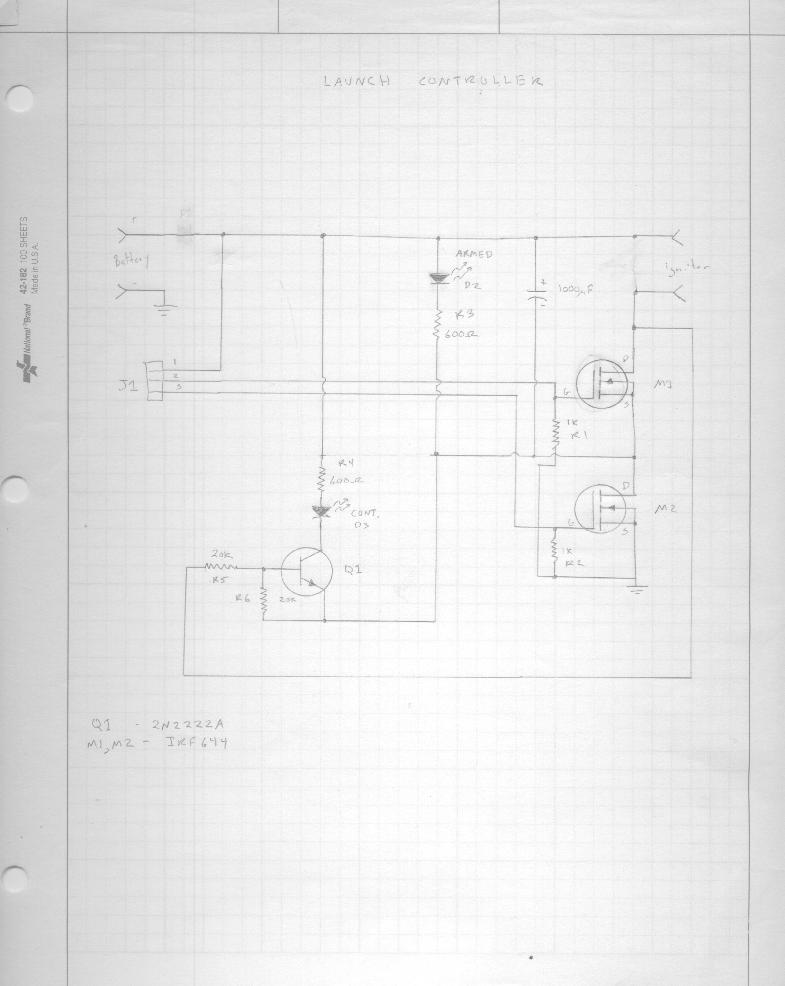
I recently found the hand drawn schematic of the relayer I built on returning to the hobby in 1995. It was pretty simple and it still works.
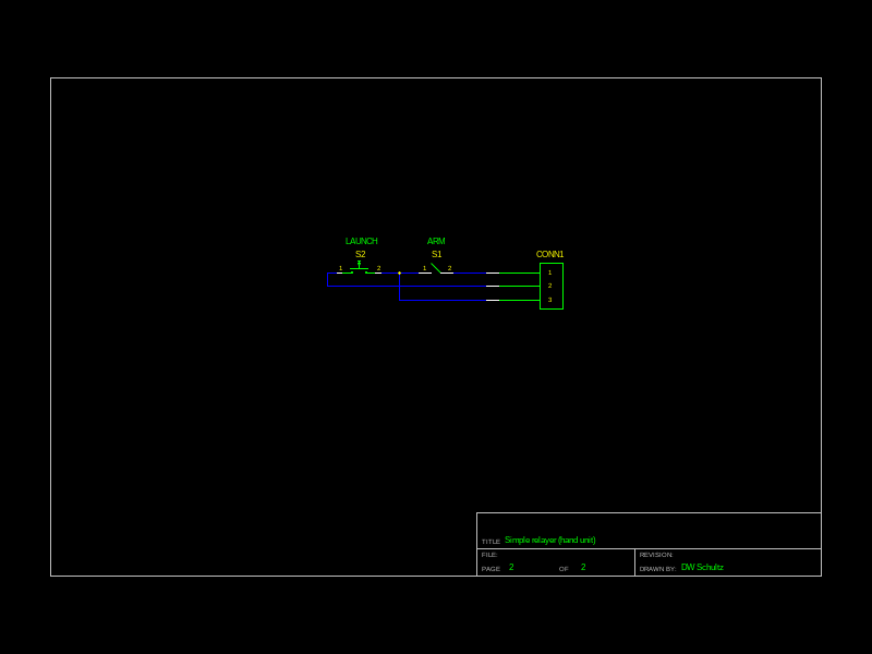
This is only the pad side electronics and the control end is just a safe/arm keyswitch and launch button. Switching to ARM turns NFET M2 on. This turns on D2 to indicate the armed condition and provides power to the continuity test circuit built around Q1. Both LEDs are high brightness types that can easily be seen in daylight.
I wanted to try out a new current limited FET and decided that this would be the perfect vehicle for it. The new FET is the VNL5050 and I am using the version in a SOT-223 package. While it claims a drain current of 19A, because of thermal limits it is actually much less. (It will start out high but then start to do a PWM thing with an average of around 8A.) I tested it with a 3 motor cluster (old Estes igniters with pyrogen, all fire current ~=4.13A) and it worked fine. I wouldn't try larger clusters and would think twice about the new Estes starters. (sans pyrogen now)
The reason for using this rather than something like a IRF1324 in a TO220 that can handle much more current is that I wanted something that would limit short circuit current. The aligator clips do sometimes touch as they fall off the rocket and the high currents possible can cause all sorts of trouble.
Since SOT-223 is a surface mount part, a PCB is in order. One with lots of copper connected to the tab to help dissipate heat. The remaining parts on the board are also surface mount. The resistors are in the 1206 package so everything is pretty easy to deal with.
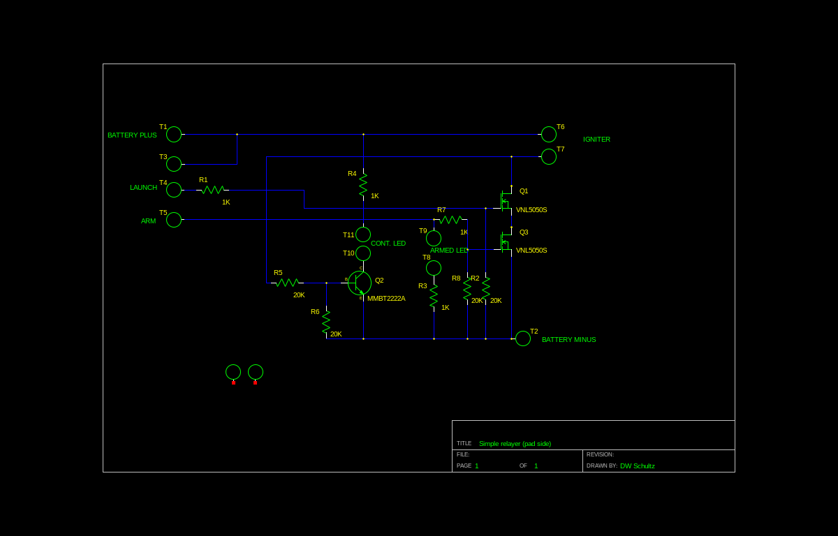
This version is slightly different in that the continuity LED is always powered. I swapped out the original high brightness red continuity LED for a new green diffused part. (WP7083ZGD/G) The red was fine but very directional. The green works very well. Too well, as it tends to wash out the red armed LED. So I will swap that out for a new difused LED at some time in the future.
The PCB in its new home:
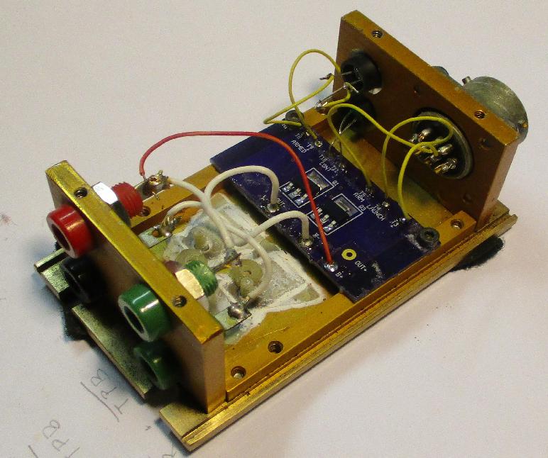
The case and connector is something I picked up at the Sandia Labs salvage yard back in the 70's. (I still remember the odd hours they were open to the general public: 1st and 3rd Friday of each month from 12:10PM to 1PM.) I recently priced a similar MIL spec circular connector and that turned out more expensive than I expected. Even though I expected it to be expensive. I worry about the lack of strain relief for the cable. At some point I will probably replace them with Neutrik XLR connectors. Cheaper by far.