
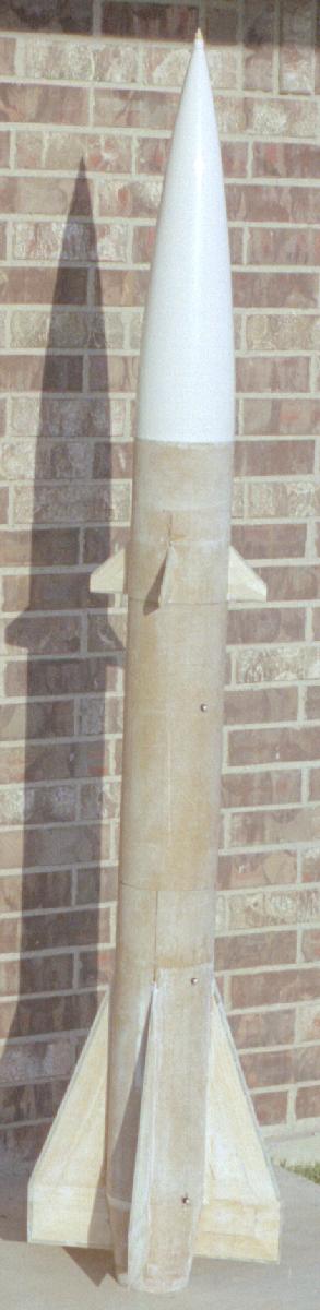
Here is a photo of the missile I am modeling. Click on the picture for a very large version. (2438X3937)
The first step in building was to simulate it in RockSim to make sure that it would work. Because the stability margin is very tight I altered the fin sizes a bit so that I wouldn't need as much nose weight.
Here is a screen image from RockSim:

And here is the RockSim file: 
And here is the RockSim file for a 4 inch diameter version:
As seen flying here.
The Airframe is a single four foot piece of PML 6" phenolic tubing. This was covered with 6 oz. and then 2 oz. fiberglass and vacuum bagged. The nose is a standard PML cone but the boat-tail is scratch built.
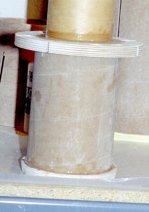
| The boat-tail started as a sheet of 1/64" ply which I cut and
rolled. I learned this technique during one of John Pursley's
sessions at NARCON. I then covered it with 6 oz. fiberglass inside
and out and 2 oz. on the outside and vacuum bagged it. Then I
slotted it for the fins.. The background in this shot has a 1 inch
grid on it so you can get an idea of the size. Click on the picture
to see a larger version.
(It is important to cut the ply in two equal sized pieces with identical grain alignment. If you cut just one the plywood grain will distort the final product. The joints have a thin strip of ply joined with CA. You can just see both seams in the pictures.) |
  |
| I cut the fins from .092 G10 sheet but then I had second
thoughts. The rear fins were very heavy at 8 oz. each. This
concerned me because more weight in the tail meant more weight in
the nose and more stress on the recovery system. After thinking
about it for a while and noticing that some nifty composite sheet
stock (from Aerospace Composite
Products) was available, I scraped the aft fins and started
over.
The composite sheet stock was made from honeycomb laminated with carbon fiber sheet on both sides. It was only slightly thicker than the .092 G10 but a 2'X2' sheet weighed only as much as one of my fins. The composite material wouldn't handle the abuse on the exposed edges so something would have to be done there. So I cut 1/2" strips of the G10 to glue to the exposed edges. Here is a picture of all of the parts needed to build one fin. A composite core, 3 G10 strips for the edges, and 4 pieces of balsa to build up the profile for air foiling. The G10 strips were just stuck on while everything rested on a flat surface. The balsa was vacuum bagged to be sure that it stayed flat to the composite. The root edge of the fin is not straight for two reasons. First is there is a notch to lock it into the aft centering ring. The second is that there is a short piece of 4" body tube inside of the boat-tail section. This provides some extra strength but is mostly there so I can recess the motor mount and motor retainer so that they will be flush with the base. The first completed fin assembly weighed in at 4.6 oz. where the blank G10 fin weighed 7.8 oz without the balsa skins. It looks like I will save about 1 pound of weight in the aft end by switching to the composite fin material. I weighed all four fins after completing them and they weighed a total of 18.2 oz so I am saving a good deal of weight. Sanding the bevels into the fins was a lot of work. I started by removing as much as I dared with a belt sander and then finishing by hand. |
  |
| Here are the parts for the motor section assembly all ready to
go together.
In front are the four fins. In the back starting from the right: Motor mount tube. Front coupler with coupler centering ring in front. Body tube with forward centering ring in front. Tail cone with aft centering ring in front. Four inch body tube section with centering rings. |
 |
| The first step in assembly was to epoxy in the centering ring
for the motor mount to the four inch tube. I am using an Aeropak
motor retainer and I used that to space the centering ring so that
the retainer is flush with the end of the four inch tube.
After that cured, the four inch tube was epoxied to the motor mount tube. The aft centering was also epoxied on and the centering ring on the back of the four inch tube for the tail-cone. It then sits for a while so the epoxy can cure. This will take a while because I used West Systems epoxy left over from working on the nose. |
 |
| The shock cord attachment for the nose is the now standard (for me anyway) method of pushing tubular Kevlar through the tip of the nose. The first step is to remove a little bit of the tip of the nose. Not too much though. The idea is to remove just enough so that the tubular Kevlar can be pushed through the hole. | 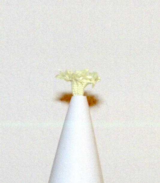 |
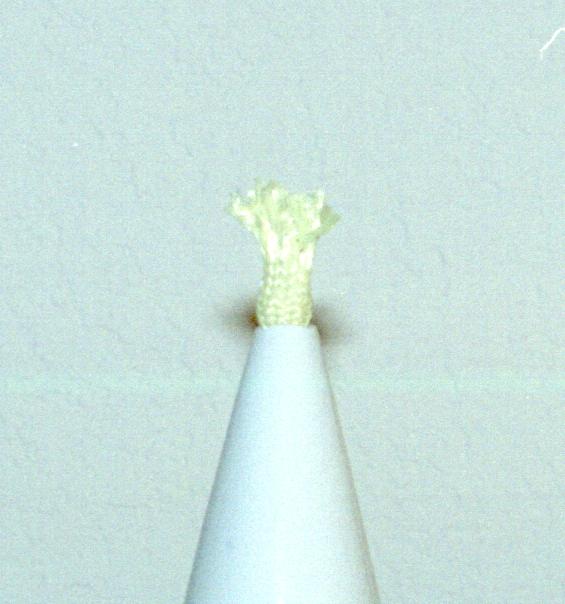
| The tubular Kevlar is pushed through and then spread. I sanded
a small piece of a handy dowel rod into a conical shape and then
pushed this into the center of the spread tubular Kevlar.
Next I put a little bit of epoxy on top of the dowel piece and then squeezed the Kevlar around it. This was shaped and held in place with some tape and a rubber band. After that cures, hang the nose by the Kevlar and pour a little bit of epoxy into the inside of the nose tip. Not too much as the idea is just to seal the hole. More epoxy will go in later when the lead weights are added. I used West Systems epoxy for this as the 30 minute epoxy I normally use is not thin enough to flow well and completely wet the Kevlar. Then the nose tip can be sanded into the final shape. This is a bit of work as the Kevlar does not sand well. |
 |
| I have thought quite a lot about the assembly sequence since I
don't want to realize I reversed steps after it is too late. The
next step is to attach the tail cone. I can't do this after the
fins are attached because it will be very difficult getting the
cone past the fins due to the balsa skins. I could do it but it
would be very hard on the balsa skins. As a result I will not be
able to fillet the fin/motor tube joint on the aft portion of the
fins. I don't think this will be a big problem because that area
will get foamed and the fins will have another 6 oz. layer of
fiberglass put over them.
I also need to attach the main shock cord mount now. This is a piece of tubular Kevlar that is pushed through two holes in the aft centering ring and then knotted. No epoxy used at all. The two part urethane foam that will fill the empty spaces should be more than enough to keep it in place. Notches are cut in the forward centering rings so the Kevlar can get past them. Here it is with the tail-cone and Kevlar cord in place. All ready for the fins! |
 |
| The next step is to tack on the fins. All I am shooting for here is to just tack them on. Structural strength is not a requirement at this point. This is mainly because the composite sheet just doesn't have a lot of contact area with the motor mount tube because of the honeycomb core. After the fins are put in place with a bit of epoxy, the body tube is put in place to serve as a support and guide for the fins. This also ensures that the body tube will slide on easily later. |  |
| Once the epoxy cures, the body tube comes off and the internal fin fillets are put in. This will take a while since it has to be done it four stages. This actually went better than I had thought. Because I expected some of the epoxy to slip past the fin, I put a tape dam on the opposite side. After the epoxy cured and I removed the tape, I discovered that enough epoxy had slipped through that I had fillets on both sides. Cool! |  |
| The next step was to start the foaming. I used PML two part foam for this. The first bit to get foamed was the tail cone. I had put a number of holes in the centering just for this purpose. Here you can see the excess foam plus some more that found gaps to sneak through. |  |
| After that I epoxied the body tube, forward centering ring and
coupler in place followed by some more foam through holes in the
forward centering ring. Since I hadn't filleted the fins, the foam
found a lot of gaps to sneak through. Cleaning up the excess foam
is quite easy once it is cured.
The motor mount tube is deliberately just a bit long. I will trim it to length after the last centering ring goes in. |
 |
| Next I installed the Aeropack motor retainer. After drilling the mounting holes I poured some more foam through the holes. This filled the gap between the motor mount tube and the four inch tube at the rear. After cleaning up the excess foam, the retainer was then attached. | |
| With the aft fins complete I then turned to the forward fins. This went a lot faster than the aft fins and I was able to cut out all of the parts (0.092" G10 cores and 3/16" balsa skins), assemble, sand in the bevels, and attach in a single evening. I cut a jig from some scrap cardboard to help align the fins while the epoxy sets up. This is then glued to the nose cone. |  |
| The last step in assembly is to add some more fiberglass cloth to reinforce the fins. While the aft fins are already pretty stiff and don't seem to need this, the forward fins definitely do or they are going to break off. Here is the first piece of 6 oz. glass going on the aft fins. |  |
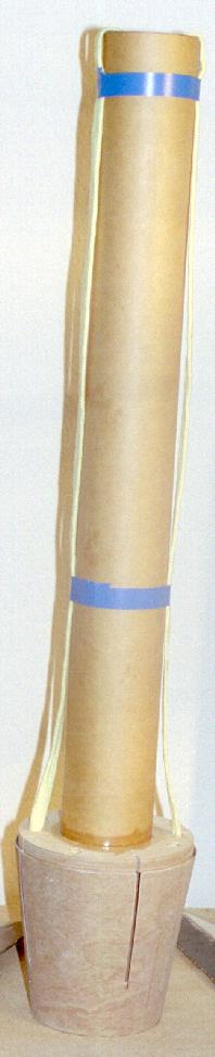
| Here is a picture of everything put together.
The two lower rail buttons are located over centering rings for extra support. The upper rail button is in the drogue parachute bay and is backed up by some plywood sanded to the profile of the tube. Holes have been drilled for 2 2-56 nylon screws used as shear pins for the drogue bay and 2 4-40 nylon screws for the main bay. There is also a bevy of holes for the payload bay. |
 |
A late (2025) note on the subject of fins. Somewhere along the way a new requirement was added to the NAR L3 rules about fin thickness: "aerodynamically stabilized using fins, tubes or other non-shroud components of measurable thickness not to exceed 10% of the mean chord or semi-span."
Ignoring the forward fins, the aft fins could violate this rule. Semi-span is 5 inches so that means no thicker than a half inch. Or is that mean semi-span? These fins are built up. Starting with a 1/8" core with balsa on each side. (Was that 1/8" balsa or 3/16"?) Then add some fiberglass and paint over the top of that. It does taper towards the tip but the root could easily exceed this unexplained requirement but I have never measured it. Good thing I did this long ago.
Thicker fins are less prone to flutter. (See NACA-TN-4197). Lots of things effect flutter. Fin shape and material being the big two. Material properties are the hardest thing to quantify. The NACA paper assumes a uniform material and this isn't. Thicker fins are better. Which is one reason to go with a built up fin. You can make an amazing fin from an all balsa core with a carbon fiber skin.
The carbon fiber is on the outside surface where it does the most good. The balsa just has to keep those two surfaces away from each other. End grain is best but difficult to source.
Another big assumption in NACA-TN-4197 is a constant thickness to chord ratio. (Flutter velocity varies as (t/c)^(3/2).) Very few fins qualify. What effect does a constant thickness fin have on flutter? Good question.