Mounted in the bay will be an AltAcc altimeter, a RDAS altimeter, and a GPS tracker.
I am trying something a bit different on this payload bay. Rather than put U-bolts in the end plates and hold them together with several pieces of threaded rod, I am running a piece of tubular Kevlar down the middle. The forward bulk plate is a 1/2" piece of plywood. I glued a 38mm centering ring to the inside of this to center the 38mm tube that runs from one end to the other. I also added an O-ring since the 38mm tube is removable.
The other end plate is a 6" to 38mm centering ring. I was quite astonished to find this as a catalog item. This plate is removable to access the interior and since it carries no recovery loads, is held in by three small bolts. Three plywood cleats with threaded inserts were glued to inside if the bay for these bolts.
This may seem a bit odd but after thinking about things for a bit, I decided that the loads on this attach point are limited. During the apogee event, the load will be limited by the shear pins holding the nose cone on. Any load greater than the strength of the shear pins will break the pins and shed the nose along with the two pounds or so of lead in it. The Kevlar then only has to retain the payload bay and a length of body tube. The loads from the main parachute opening will not be large because the Rocketman parachutes open fairly softly.
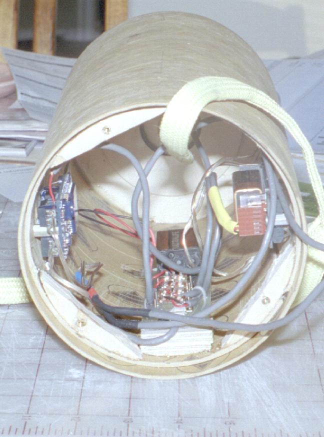
At the bottom of the tube is the power and arming board. This board holds the RDAS battery and four switches to control power to the AltAcc and RDAS. See Schematic. The board is built from .092" G10 sheet and is screwed to plywood cleats that are glued to the coupler. The battery is retained by Velcro and zip tie.
In order to prevent confusion between the drogue and main outputs of the altimeters during preparation, I have attached short wiring harnesses to both altimeters that are never removed. These terminate in polarized four pin Deans connectors. The electronics bay contains wiring to connect these to the output connectors in the drogue and main parachute compartments. (Schematic) Two pin Deans connectors are used in the parachute compartments.
Using connectors for the ejection charges requires a little bit of extra prep on the charges but makes the assembly process in the field go a lot quicker. I am not concerned about the connections falling apart because the contacts are gold plated and designed for using in RC aircraft which have horrendous vibration problems.
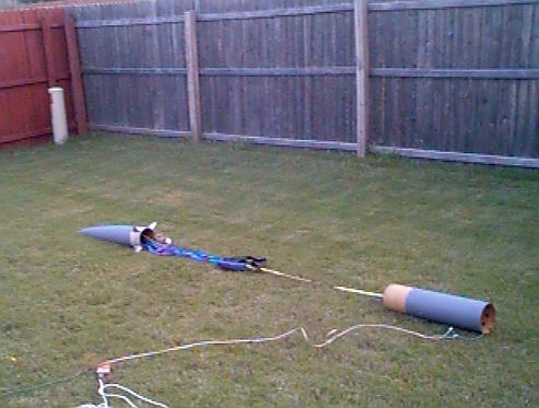
Here is a picture of the main recovery system spread out on the floor. This is the first cut at connecting everything.
In the front is the coupler that holds all of the electronics. You can see the tubular Kevlar entering the 38mm tube.
On the left is the deployment bag with a Rocketman R7C parachute in it. The deployment bag lanyard is tied to the coupler and the shroud lines go to the nose. The nose cone has a short (10") length of body tube attached to it.
On the right is the Rocketman R12C parachute in a deployment bag. Lanyard to nose and shroud lines to coupler. After looking at this arrangement for a bit, I decided to extend the lanyard on the R12C deployment bag. From this picture you can see that the parachutes would be almost side-by-side when they are pulled from their bags. I decided this is probably not a good thing.
Part of the reason for recovering the nose on a separate parachute is that the rocket will be a bit heavier than the maximum recommended weight for an R12C. The empty rocket is already close to twenty pounds and adding an expended motor puts it over the 20 pound rating of the parachute. Putting the nose on its own parachute removes about 5 pounds from the load on the R12C.
I haven't tried this before but I don't expect to have any problems with it. I will fly this on something besides an M motor for a test flight so that I don't totally embarrass myself on the M. I couldn't locate a reasonable K motor so the first flight will be on an Animal Motor Works L1060GG.

The Aerocon capsules I am using only hold 2 grams of BP. Since this is about what I expected would be required to shear the 2 2-56 nylon screws holding the drogue bay in place, that is where I started. Except with Pyrodex. Prepping everything for this test was a pain. Of course, I just realized that there was a simple way to make it a lot easier. I hate it when that happens. :-)
The Pyrodex did shear the pins but didn't separate the two sections. I called this a marginal success and moved on to the main parachute bay because it is held in place with 2 4-40 nylon screws.
This was a total failure for the Pyrodex P as the shear pins didn't shear. I then prepared a 2 gram (same volume) BP charge to see what would happen. You can see the results in the picture to the right. Total success.
This was what made me rethink the parachute setup some more as the R7C lanyard is what stopped the payload bay. By connecting the R7C lanyard to the top of the R12C, the R12C should be out of the nose, or at least out of its bag, before the lanyard slows things down.