There is little good information available on where to locate rail buttons on model and high power rockets. After answering a question on the DARS forum on this recently and getting some push back I decided it was time to provide a more substantial description.
A rocket will typically have two and sometimes more rail buttons on them so that a rigid rail can provide guidance in the early part of flight. But little consideration is given to the dynamics when only the last rail button is in contact with the rail. Once the first button leaves the rail, the last button is doing the rocket no good. This aft rail button establishes an axis of rotation and the correcting forces resulting from forward motion and more importantly wind act on the rocket. In typical installations the center of pressure is ahead (sometimes well ahead) of the aft rail button.
This is equivalent to having a CP ahead of the CG so the rocket will turn away from the wind. Depending on conditions, this could result in the rocket having a substantial angular velocity when it departs the rail. Getting a good idea of the details requires a good simulation but so far as I can see no currently available rocket simulation program (even the $1,000 Rocksim Pro) that deals with these dynamics. So the best that can be done for now is an approximation.
The resulting rotation of the rocket is usually not too large but it is an aspect of the system dynamics that is overlooked. If ignored it could result in a rocket going somewhere unexpected. Fortunately there is a simple fix.
(Note: I am using mathcache for the equations here since it is simpler than creating a text file for each equation and then running tex2gif. Hopefully they will render as well for you as they do for me.)
For the first example I will present one of my rockets in the form of a PML kit for a two stage rocket. I last flew this in 2005 and while it is difficult to tell from the photos, this flight turned away from the wind which was from the south or right in the photos. It is certainly suggestive but since the orientation of the camera isn't known, you can't tell for sure. (My recollection of the flight is that it did indeed turn.) I built this well before this problem was brought to my attention so the rail buttons are not well located. Although they are located in a way to demonstrate this problem quite well. An image captured from Rocksim showing the configuration:
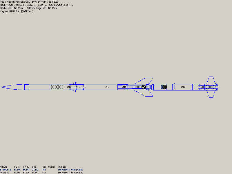
This is slightly different from the stock version since both motor sections are anti-zipper and the upper stage is dual deploy. The interstage is also slightly longer to accommodate a Gwiz altimeter.
Using information from Rocksim it is possible to estimate the rotation as it comes off the rail.
Rocksim information:
Rocksim provides its estimate of the moment of inertia around the center of mass using the material information it has. This isn't completely accurate but it is the best information available. This needs to be corrected using the Parallel Axis Theorem to get the moment of inertia around the aft rail button which is the axis of rotation.
$$ I = 56000\,{oz}\cdot{in^2} + 101oz\cdot{30\,in}^2 = 147000 oz\cdot{in}^2 $$
Plotting the flight data shows that the pitch force is 25N (using a 15 mph wind setting) at the time the aft rail button departs the rail. Velocity at this time is 70 ft/sec. Both of these values are changing in the time before this but constant values will be assumed and shouldn't be far wrong. Time spent with just one button on the rail:
$$ t=\frac{17\,inches\cdot\frac{1\,foot}{12\,inches}} {70\,feet/sec} = 0.02s $$
The angular acceleration during that time will be:
$$ \alpha = \frac{F\cdot r}{I} = \frac{25N \cdot 0.71m}{2.69kg\cdot {m^2}} = 6.6\, radians/{sec^2} $$
Which is a pretty healthy value. Keep that up for very long and there will be trouble so it is a good thing this lasts only 20ms.
$$ 6.6\, rad/{sec^2} \cdot 0.02\,sec = 0.13\, rad/sec \,or\, 7.56\, degrees/sec $$
During this time the total rotation (assuming constant acceleration) is about 0.08 degrees. Which is close enough to zero as makes no difference. The problem is that this angular velocity continues until it is damped out by the rockets natural stability. Which takes time. Worse is that angular momentum is always conserved.
Angular momentum adds an interesting twist. As the rocket leaves the rail it is rotating around the aft rail button but aerodynamic forces on the unconstrained rocket cause it to rotate around its center of mass. These two axis of rotation have quite different moments of inertia. Because angular momentum is conserved the rotation around the button is equivalent to a higher rate of rotation around the center of mass. Which means that it takes more time to dissipate this angular velocity. This is a dynamic process but simply adjusting the rate of rotation for differing moments of inertia should give an idea of the size of the effect:
$$ 7.56\, degrees/sec \cdot \frac{147000}{56000} = 19.9\, degrees/sec $$
The restoring force is the same to start with (25N) but the moment arm is now the distance from the CG to CP rather than aft rail button to CP. Since this is much shorter, the torque is lower. It is going to take some time to compensate for this initial angular velocity.
While the first example used a long thin (and two stage) rocket, this is a short, fat, and far too heavy rocket: my ill fated ATACMS, the L330 version. (Follow that link for design details.)
Information from Rocksim:
The corrected moment of inertia is 98,000 oz-in.2 or 1.79 kg-m2. Angular acceleration is 1 rad/sec2 for 30ms resulting in an angular velocity of 0.03 rad/sec. (1.7 degrees/sec)
Even though this rocket is much shorter and the moment of inertia is very sensitive to length because it is proportional to distance squared, the moment of inertia is not much smaller than the BBX. There is a shorter moment arm for the torque resulting in a lower angular velocity. So while this rocket had serious dynamic stability problems, there was very little rotation induced by interaction with the rail. In addition, because the distance from the aft rail button to the CP is about the same as the CP to CG distance, the torques are similar. So it should take less time to damp it out.
There are two things that can be done to minimize this effect:
You can limit the time this torque is applied by minimizing the time that only one rail button is on the rail. You don't want to go too far in that direction so a distance of about 1 caliber should work well.
The second way to minimize this rotation is to minimize the moment arm. Locating the aft rail button at the CP (or close to it since it isn't stationary) will do this.
Combine these two and putting the rail buttons at the CP and CG should do nicely.
I computed the estimate of angular velocity for a better button location on the PML Terrier-Mini BBX. I tried moving the aft rail button to the top of the interstage where I could drill into the shoulder of the transition. This resulted in about half the angular velocity. Which is better than it appears. Because the energy of this rotation varies with the square of angular velocity, it should take about one quarter as much time to damp it out. Add in the effects of the lower moment of inertia which also figures in the energy and I would expect less than one tenth as much total rotation. Which isn't too bad.
Estimating the rotation rate coming off the rail is easy compared with what happens afterwards. I have been digging around and while I have found some information on this and the related problem of tip off in artilary rockets I have found no rigourous treatment. Or at least nothing published on the web. I may purchase a copy of Topics in Advanced Model Rocketry in the hope that it will help.(It didn't.)
At this point I think that simulating this will require adding at least one degree of freedom to the simulation. The rotation around the aft button axis being that extra degree. This rotation would then gradually die out due to damping.
A related phenomena is tip-off from gravity when the rail isn't vertical.
$$ torque = W\cdot cos(QE)\cdot d $$
W is the weight of the rocket, QE is the rail elevation angle (90 degrees is vertical), and d is the distance between the rocket CG and the aft rail guide.
Note that the moment arm is from the CG to the aft rail guide so is longer than for wind which means that the effect will be greater for an equivalent force.In the example of the Terrier-BBX above, the force is equivalent at an angle of about 80 degrees. (10 degrees off vertical)
Moving the aft rail button reduces the moment arm and the time the torque is applied. It cannot be reduced as much as for the case of wind applied torque but it can be decreased a lot. The problem can be eliminated if the rail is designed for simultaineous release.
The current NAR recommended practice is to set up the flight line parallel to the wind and angle the rod/rail 5 degrees away from the flight line. Which prevents you from angling the rocket into the wind in an attempt to have these two effects offset. Instead you get both. In most cases this isn't a big deal but it can have a large impact on where the rocket lands. (Note that the simulations performed by NAR when coming up with that 5 degree angle did not include either of these effects.)
Besides the launch dynamics you might also want to consider the static loads. Rail buttons that straddle (fore and aft) the CP will minimize the wind loads on them. The load will split between them so that the sum equals the wind load. But if they are both behind the CP (the most common configuration) then the lever action will result in loads in excess of the wind load. The vector sum will be the same but one will be in the opposite direction of the other. Not a problem if the buttons are well attached to structure.
The same applies to the loads from the weight of the rocket as you slide it on a horizontal rail.
Or consider the fate of the Estes Mean Machine. This has launch lugs located well aft of the CP. I can't remember how many Mean Machines I have seen refuse to leave the rod thanks to the torque on the lugs from a breeze.
Home