At a recent club meeting one of the members told a tale of woe about losing a rocket at LDRS. Presumably due to the failure of the RDAS Tiny to activate the ejection charge. After I asked a few questions it was clear to me that the output FETs had failed on a previous flight.
The RDAS manual simply states a max current on the outputs of 2.5A but it does not explain the reasoning behind that limit, which is crucial. A naive user would simply assume that the output current was limited somehow by the altimeter to 2.5A. But in fact the problem is that the altimeter in no way limits the output current (The RDAS Classic could be configured to limit the output current to 1 Amp. Neither the Compact or Tiny version have this capability.) and if it exceeds that current, it could damage or destroy the FETs.
If the internal capacitor power source is used there is no problem because of the limited energy. But if you decide to bypass that capacitor and use an external battery, the FETs are in serious danger. The problem is the result of the FETs being packaged in very small SO-8 packages. This package simply cannot dissipate very much power. It is up to the user to limit the device current to safe levels. It is not sufficient to make sure that the igniter being used will never draw excess power unless it can also be guaranteed that a short will never happen. If the wires to the igniter short circuit while the FET is on, failure is very likely.
I looked at my RDAS Compact and it uses a NDS9953 SO-8 part for the output and I assume that the Tiny uses a pair of these dual P channel devices. (It certainly uses two SO-8 packages. If anyone knows the actual part number, tell me so I can correct this.) For reference, here is the data sheet for the current version of this part.
I was a little surprised to see a P channel device being used as this requires an extra driver stage between the micro-controller and output FET. (More discussion on P and N FETS here.)
The data sheet shows that Rds(on) with 10V of gate drive is about 0.1 Ohms. Since the 9V battery internal resistance (plus the igniter of course) is much greater than this the current is limited by these external elements and not by the P FET. A short could result in very large currents.
The device does have a specified maximum continuous current but that isn't important as this is a pulsed application. For that you need to look at Figure 11. Using this figure you can find the effective thermal characteristics with different pulse widths.
With a 0.1 second pulse the effective thermal transfer factor is 0.07 * 135 C/W or 9.45 C/W. A one second pulse is 27 C/W. (The manual indicates that the RDAS uses a one second pulse.)
Maximum junction temperature is 150C. If the ambient temperature is 30C then only about 4 Watts of power dissipation are needed to exceed the maximum temperature with a one second pulse. For a 0.1 second pulse it is 12.7 Watts.
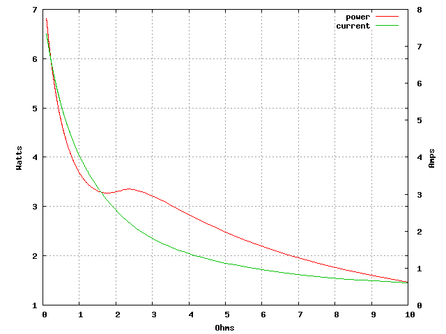
The interaction between Vgs and current makes it tricky to figure the power dissipation. So I dusted off my SPICE simulation skills. Fairchild Semiconductor provides (in a roundabout way) SPICE models for their parts so I grabbed the one I needed. It doesn't seem to have a robust thermal model or Rds would increase as the part heated up. I created a simple circuit to test the FET. I then varied the resistance in series with the 9V power source to the FET and plotted the results:

I don't show any data for less than 1 Ohm as the current is rising so rapidly that it gets out of hand. (>100 Watts at 0.1 Ohm) Including it in this plot would obscure the detail.
One of the lines in the device model disagreed with my version of SPICE so I had to try and figure out what it was doing and fix it. It may not be correct but the results don't look completely wonky even if they don't vary Rds(on) with the rising device temperature. I use a voltage controlled current source to simulate a voltage controlled resistor so I can sweep through resistor values. Otherwise it must be done slowly by hand. One detail of this is that the resistance is actually the inverse of the controlling voltage. (I = V/R)
It is clear that a brief short circuit with a low resistance power source is going to fry this part. Even a brief short with a 9V alkaline battery is a problem.
The power dissipation limit is for the package and there are two FETs per package. If both FETs are on at the same time or with very little delay, then the per device dissipation limits will be even lower.
The BlackSky AltAcc uses a similar part (same package, different device, similar power dissipation specs - NDS9936) and a 9V battery but it keeps the output on for only 0.1 second. Because the gate drive in the AltAcc is from the regulated 5V supply (which has a capacitor to hold it up), the gate drive is not affected by battery internal resistance. So Vgs is a constant 5V. This makes computing power dissipation a snap. Worst case Rds(on) at 125C is 0.099 Ohms. Power dissipation would then be 3.2W which is no problem at all for a 0.1 second pulse. Or even a 1 second pulse.
There are several things that AED could do to help with this problem. Here are a couple in order from easiest to hardest:
If the on board firing capacitor has sufficient energy for your pyro device, use it. It limits the firing energy to safe levels for the output FET. I have always configured my RDAS Compact this way and it hasn't failed. (Yet. I hear the pessimists say.)
If you must use an external battery, add a series resistor. This resistor should be chosen to keep the FET within its Safe Operating Area even if the output is shorted but allow sufficient current to operate the pyro device reliably.
Ideally you would add a series resistor to each output (pins 5-8) especially if more than one will be on at a time, but you could use a single resistor. This single resistor must not be in series with the safe/arm switch on pin 4. Doing that will increase the loss of Vgs as current flows and severely reduce current output capability along with increasing power dissipation in the FETs. Instead the single resistor should be in series with the common connection to battery ground. I have reproduced here Figure 3 from the RDAS Tiny addenda with an added note showing where a single resistor would go. Because this resistor is outside of the connection between the altimeters ground and the pyro battery ground, it will not reduce the gate drive.

The series resistor(s) will of course also have power dissipation problems. Check the specifications as most resistors are rated for brief overloads.
Adding a resistor in series with the low side alters the Vgs drive so a new simulation is needed to analyze this situation. I altered my SPICE file to add a 1 Ohm resistor between the Q2 drain and ground. The resistance in series with the power source is then varied as usual producing:
Just this simple 1 Ohm part makes a big difference in the power dissipation in the FET. It stays below the 4 Watt limit for a supply resistance down to slightly less than 1 Ohm. This is more than adequate for 9V alkaline batteries. (Note that current with a typical 9V battery resistance of 1.5 Ohms and a typical 1.6 Ohm electric match is greater than 2 Amps which is plenty of margin.) Power dissipation in the 1 Ohm resistor is simply I2R. At 3 Amps that is about 9 Watts which is much greater than what typical resistors can handle. A 1 Watt wirewound resistor is probably the best choice. In normal operation its dissipation limits will not be exceeded.